Hardware and Software Integration: Autonomous Mobile Robot DIY Guide

Welcome to the second installment of our DIY Autonomous Mobile Robot (AMR) guide. If you haven't read the first part yet, we recommend checking it out before continuing.
Hardware and software integration
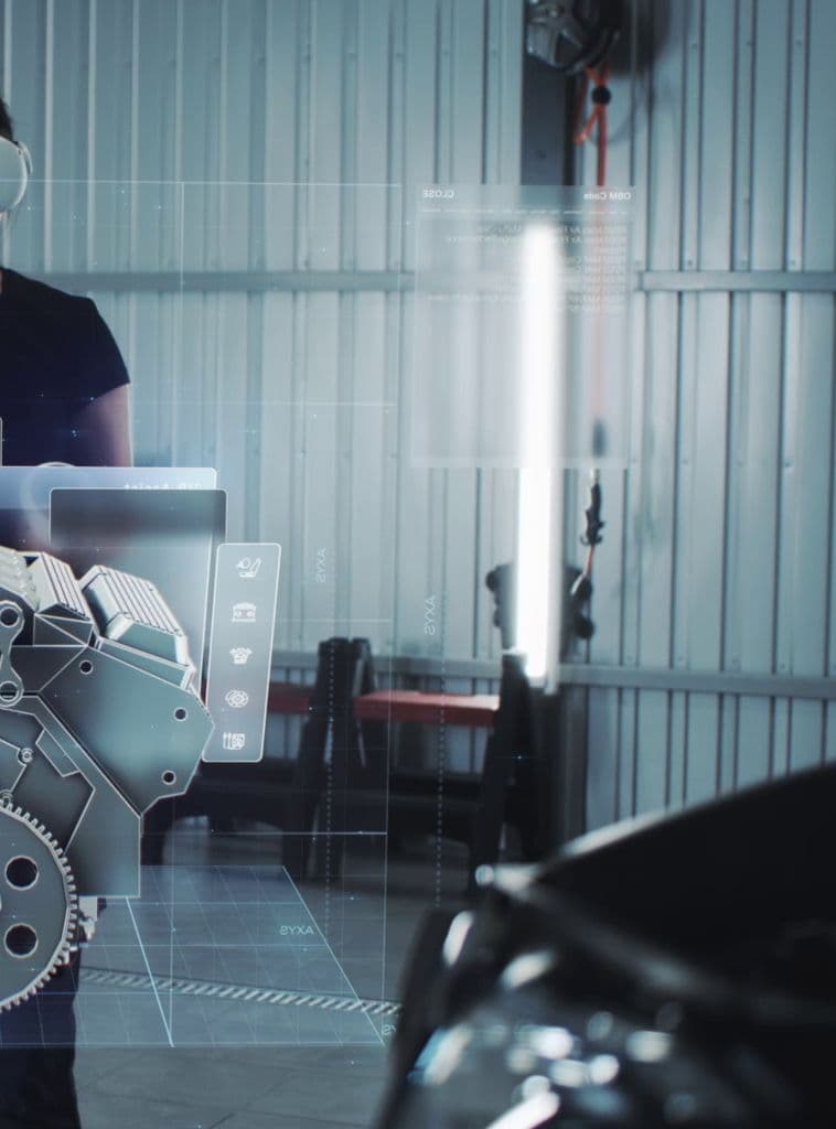
Once the mechanical parts of the robot are successfully manufactured and assembled, we can proceed with the installation of electronics, wiring, and configuring components. Our project uses the Linorobot open-source software packages and hardware, which has a large community and is user-friendly, even for non-professionals.
Picture 1 shows the electronics block diagram and overall system architecture.
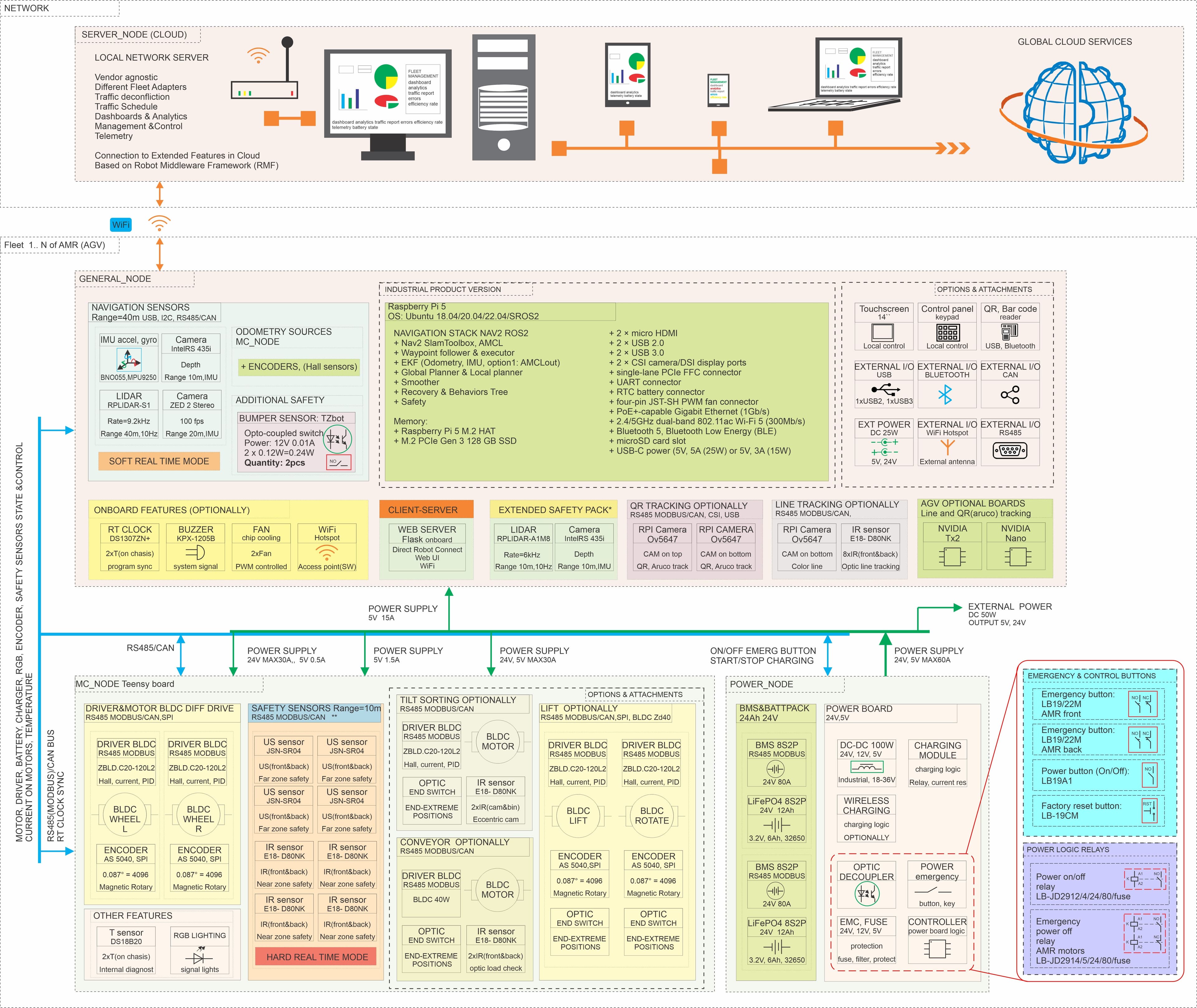
Picture 1 - OpenAMR mobile robot HW architecture
List of the hardware сomponents:
- Main single board computer (SBC)
- Safety sensors (US, IR, bumper), RPI camera and LiDAR
- Controller Teensy board and firmware
- BLDC motors, drivers and encoders
- Batteries, Battery management system (BMS), and wireless charger
- On/Off switch and Emergency button
- Other components
The components depicted in the hardware diagram can be found in the datasheets folder. Indicated suppliers have been tested and proven reliable.
Comprehensive details on setting up the software, hardware, and firmware can be found in the wiki section on the following GitHub page.
Main computer: Raspberry Pi 5
Finally, in the new version of the Raspberry Pi 5, it's possible to use SSD memory connected via PCI Express. This not only increases the speed of data exchange but also enhances the reliability of this single-board computer, especially for industrial applications. The Raspberry Pi 5 is also available in various housings that provide greater dust and moisture resistance.
By the way, the usual method of using an SD card is also suitable. However, keep in mind that the SD card can wear out quickly, and the contacts may oxidize or come loose over time due to increased vibration, which is unlikely but still possible especially in a real industrial environment.
Safety sensors (US, IR, bumper), RPI camera and LiDAR
On the hardware diagram, you can see the main components used in mobile robots, as well as recommended options.
For mapping, robot localization and navigation, we use LIDAR, ROS2 (Robot Operating System) navigation stack and SLAM algorithm. LIDAR is also used to detect dynamic obstacles, ensuring the safety of the robot's movement for those around it. You can start with the cheapest RPLIDAR A1 with a range of up to 12 m, but it is recommended to use LiDAR with a longer range, which you can also choose from the same manufacturer on their SLAMTEC website.
To detect objects, people, and animals in the robot’s path, ultrasonic detectors are used for distances up to 3 meters, and IR sensors are used for distances up to 80 cm. Together, these sensors ensure the safe movement and turning of the robot. Correct sensor placement is crucial to ensure peripheral vision during turns, as LIDAR covers only a thin strip in height and is configured to detect obstacles ahead with a 120-degree viewing angle.
It is important to note that LIDAR operates at a certain height (about 30 cm) and with a 120-degree angle. Therefore, the use of ultrasonic and IR sensors is essential for ensuring traffic safety. If you place a box on top of the robot that is larger than the robot itself, ensure that the sensors cover this area as well. What is also important is to set up correct dimensions for the robot in the description file URDF - in linorobot2_description/urdf directory you can change the values according to the robot's specification/dimensions.
Optionally, you can also use a bumper, the model of which is indicated on the hardware diagram.
Don't neglect safety and place the emergency stop button in a visible location.
Let's take a closer look at connecting the motors, drivers, batteries, BMS, wireless charging receiver, and other components at the lower level of the hardware diagram.
BLDC motor and driver
You can find the documents for the motors and drivers in the shared folder with all documents. The most challenging tasks are likely connecting the motors to the driver and the driver to the controller. The second most difficult task is connecting the batteries and the BMS. Everything else is relatively straightforward.
The BLDC motors offered are controlled using drivers. The control signal to the driver can be transmitted in the form of PWM or via an RS485/CAN interface. In the proposed open-source project Linorobot, control occurs via PWM. Please check Picture 2 for detailed information on wiring and control of the ZD driver and ZD BLDC motor. If you decide to use a ZLTEch hub motor - please check the corresponding folder for all detailed ZLTech datasheets.
In case of using ZD drivers and motors, you will most likely need to install and connect encoders on each wheel. You can also read the Hall sensor feedback from the motor, but only in RS485 or CAN mode. This feedback may be enough to get a signal with sufficient feedback resolution from the wheels. An encoder is used to measure the number of wheel revolutions per minute, you can use any magnetic encoder. In our case, it is the AS5040A or AS5600 and a radial magnet. You can buy any board with such an encoder and secure it in a 3D-printed fastener, which you will find in the documentation in the general storage 3D models. The magnet is glued to the shaft, and the sensor is placed in close proximity to the magnet.
Knowing the dimensions of the wheel, you can easily calculate the distance traveled. However, wheels can sometimes slip or spin unevenly due to uneven surfaces, uneven loads, and other factors.
Therefore, we use several sensors to track the trajectory, acceleration, rotations and movement of the robot, such as an IMU and LIDAR with the SLAM algorithm. All these sources of odometry converge into a particle filter, specifically a Kalman filter. The purpose of this filter is to fuse the input signals from the three sources, providing a more accurate result than each source would individually.
As mentioned above, feedback can also be obtained from Hall sensors located inside the motor. This signal can replace the encoder signal. Although the encoder usually provides higher resolution, feedback from Hall sensors is usually sufficient for most robot applications.
You can find complete documentation on motors and drivers in the general document repository. This chassis uses a motor and driver from ZDmotor.
The connection and configuration of the motors are described in detail here. Pay attention to the PID settings, as they are crucial for ensuring accurate movement.
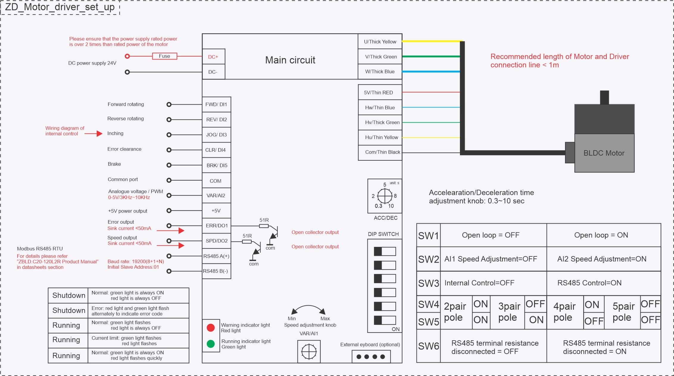
Picture 2 - Wiring diagram for the ZD BLDC motor and driver
The versatile design of the OpenAMR can be adapted to create different types of robots for various logistics tasks, making it ideal for automating the movement of goods in small and medium-sized businesses. It can also be modified to carry tools or a roller cage, increasing its usefulness in a variety of scenarios.
One of the most commonly used and useful mechanisms is the elevator, which allows you to raise, move, and lower shelving units. Such a mechanism can be designed based on a simple scissor lift solution, though this design has a number of limitations.
Alternatively, you can use a ready-made module from the TZbot company. More information about different features and additional components that you would probably need you can find in the TZBot folder. This manufacturer can provide you with affordable components such as batteries, BMS, lifting or hooking mechanisms. You can also consider DalyElec as a reliable BMS supplier.
Conclusion
The cost of this robot does not exceed $3,000, making it a prime example of a low-cost DIY autonomous mobile robot suitable for industrial automation or warehouse logistics. Open-RMF can be used to integrate robots into a fleet.
When assembling the robot, you may have questions - this is normal. Most of the answers can be found in this guide upon re-reading, as well as in the description of the open-source project for Linorobot. For more detailed topics, basic knowledge can be obtained through online research. It is not feasible to cover every detail comprehensively at a basic level, as this article is intended to provide an overview rather than a complete robotics textbook.
This project requires basic knowledge of electronics, software, and mechanics. If you have any questions, comments, or want to discuss robotics, connect with us on LinkedIn.
The robot and its design were tested in real conditions. Based on the testing results, the design was optimized and manufacturability was increased.
These files are distributed without any express or implied warranty, including of merchantability, satisfactory quality and fitness for a particular purpose.
What's coming next
In the upcoming article of our AMR (Autonomous Mobile Robot) building series, we'll cover:
- Robot UI Design
- Core Functionalities
- Architecture Breakdown
- Final Assembly
Stay tuned for this comprehensive conclusion to our AMR building journey!