Getting Started: Autonomous Mobile Robot DIY Guide for Small Businesses
Introduction
Small and Medium Enterprises (SMEs) across various sectors can greatly benefit from the Autonomous Mobile Robots (AMR). In warehouses and distribution centers, AMRs automate goods movement and order fulfillment, optimizing logistics with a goods-to-person approach. Manufacturing plants enhance their production workflow through efficient material transport and logistics. Small family farms and greenhouses utilize AMRs for moving crops, feed, and equipment, improving operational efficiency.
One of the most famous and successful stories of the early adoption of autonomous robots is the Kiva Robotics story. Founded in 2003 and acquired by Amazon in 2012 for nearly 800 million USD, they pioneered the industry and the goods-to-person concept.
Imagine transforming your business operations with a custom-built robot that you can assemble in just a few days. Picture the satisfaction of witnessing a robot you constructed autonomously navigating your facility, handling repetitive tasks, and allowing you to focus on more critical responsibilities. This isn’t merely a vision - it’s a project you can initiate today.
This series empowers you to build your own AMR using open-source designs and accessible manufacturing methods.
Follow our step-by-step guide featuring detailed drawings, 3D models, Bill of Materials (BOM), hardware architecture, navigation software and user interface packages. Utilize straightforward manufacturing technologies to integrate advanced automation seamlessly into your business operations.
The project aims to strike a balance between implementation complexity and achieving high-quality results. Our goal is to provide straightforward and cost-effective instructions for creating a professional-grade mobile robot suitable for real-world applications. Take it step by step and stay patient throughout the process.
Having mastered this guide, you can confidently advance this area independently and potentially enhance productivity not only within your enterprise but also for your partners.
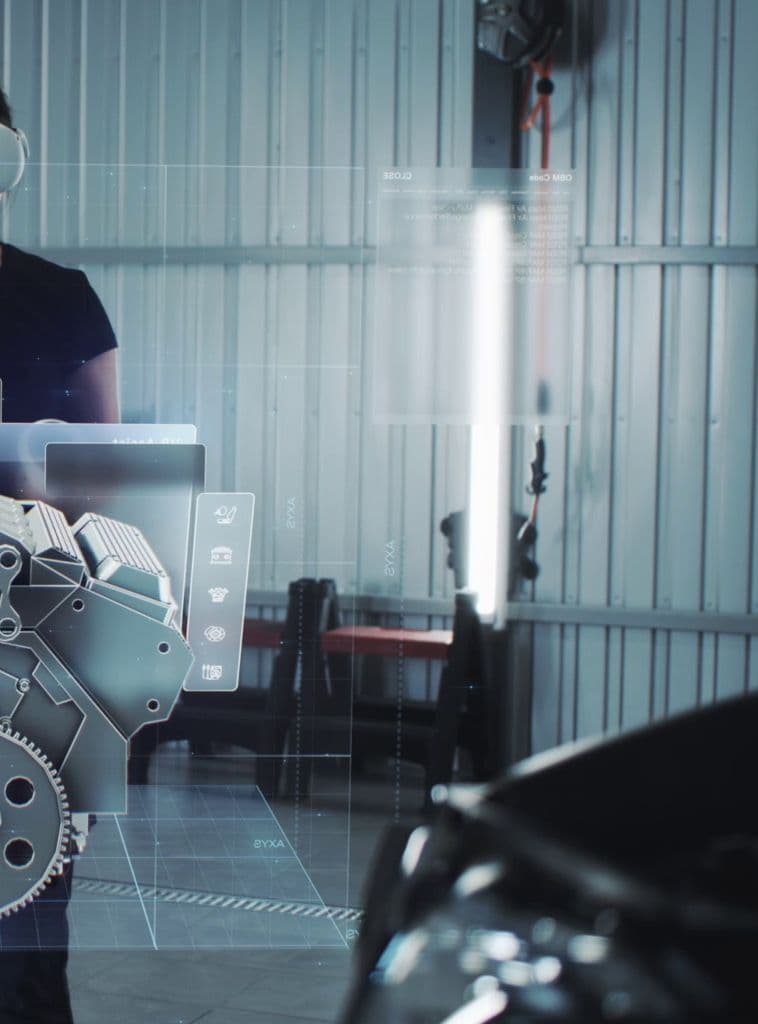
In Picture 1, you can see what the completed project should look like. The conveyor is a separate feature and is not discussed in this article. However, you can independently install and connect any mechanism or extension to the mobile platform to give it the functionality you need. For this purpose, a mounting platform and holes for wire routing and connector installation are provided in the upper part of the robot.
Picture 1 - Mobile robot general view
If we look at other similar projects to create your own AMR, they often offer incomplete or limited solutions, for example, purely software options, devoid of electronics and mechanics, or kits suitable only for R&D and training due to the non-functionality of the body and mechanics. Commercial solutions often require additional payments for completion or use of the project.
However, it would still be beneficial to gain experience by researching projects like SEER, SlamTec, Roboteq, Ubiquity robotics, and Bosch Rexroth Rokit.
Our goal was to develop a simple, cost-effective and comprehensive solution for basic warehouse and production automation. Our design and software have successfully passed basic testing in real production conditions.
By open-sourcing our technology, we provide SMEs and individuals with an opportunity to leverage advanced robotics without the high costs associated with research and development.
Manufacturing, chassis and mechatronics: How-to guide for the OpenAMR robot
Design and manufacturing approach
Perhaps one of the most important components of this series of articles is the design of the mobile platform. The project may seem cumbersome, and it is, because this project is closer to a professional one than an amateur one.
Don't be intimidated by the volume of information - you always need to eat an elephant in parts. Moreover, we will try to help you and answer your questions.
The key features and capabilities are described in Table 1.
| Characteristics | Value |
|---|---|
| Navigation type | LiDAR/SLAM |
| Robot platform drive type (cinematics) | Differential drive |
| Total weight of the conditional robot model | ~ 60 kg (~ 132 lb) |
| LiDAR view | 120° |
| Linear velocity without load | ~ 1500-2000 mm/s (~ 59-79 in/s) |
| Linear velocity with full load (120kg+) | ~ 1200-1500 mm/s (~ 47-59 in/s) |
| Positioning accuracy SLAM (indoor) | +/- 50 mm (± 2 in) |
| Platform dimensions | 600 x 800 mm (24 x 31.5 in) |
| Supply voltage, nominal | 24/48 V |
| Battery capacity (LiFePo, Li-Ion) | ~ 48-56 Ah |
| Battery life, not less than | 6 hours |
| Communication channel | Wi-Fi (2.4/5 GHz) |
| Load, up to | 120 kg (265 lbs) |
| Operating temperature | -10°C to +50°C (14°F to 122°F) |
Table 1 ⎼ Electromechanical characteristics
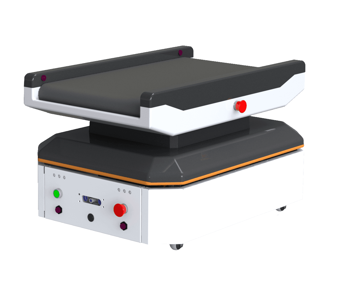
Picture 2 - Mobile robot assembly overview
General steps to produce chassis
Our design is optimized for manufacturability, requiring only basic technologies such as:
- Laser cutting
- Bending
- Turning works (optionally)
- 3D printing (optionally)
- Assembly
Using mostly 2mm thick metal sheets, the design is robust yet simple to produce, allowing one person to build the robot in just one day if every part is already produced.
The top of the robot features a mounting place for installing and connecting various external modules, such as:
- Conveyor
- Tote
- Pulling hook
- Elevator
- Tilting mechanism
- Other custom modules
Attention!
Sheet metal parts vary by production. Currently, the parts are designed for the following coefficients and radii:
K=0.47:
sheet 0.8 mm - R=1.2;
sheet 1.2 mm - R=1.5;
sheet 2.0 mm - R=2.4.
After bending, parts can be painted.
After painting, we install riveting nuts. It is allowed to install riveting nuts before painting, provided that the threaded part of the nuts is protected from coating.
Screws installed without lock washers - fix with a thread lock (eg Loxeal 55-03).
Mobile platform assembly guide
Downloadable resources
- Production drawings, 3D models, STEP, and DXF files
- Specification sheet, including all parts and assemblies, sensors, and fasteners, links to components
Fabrication Process
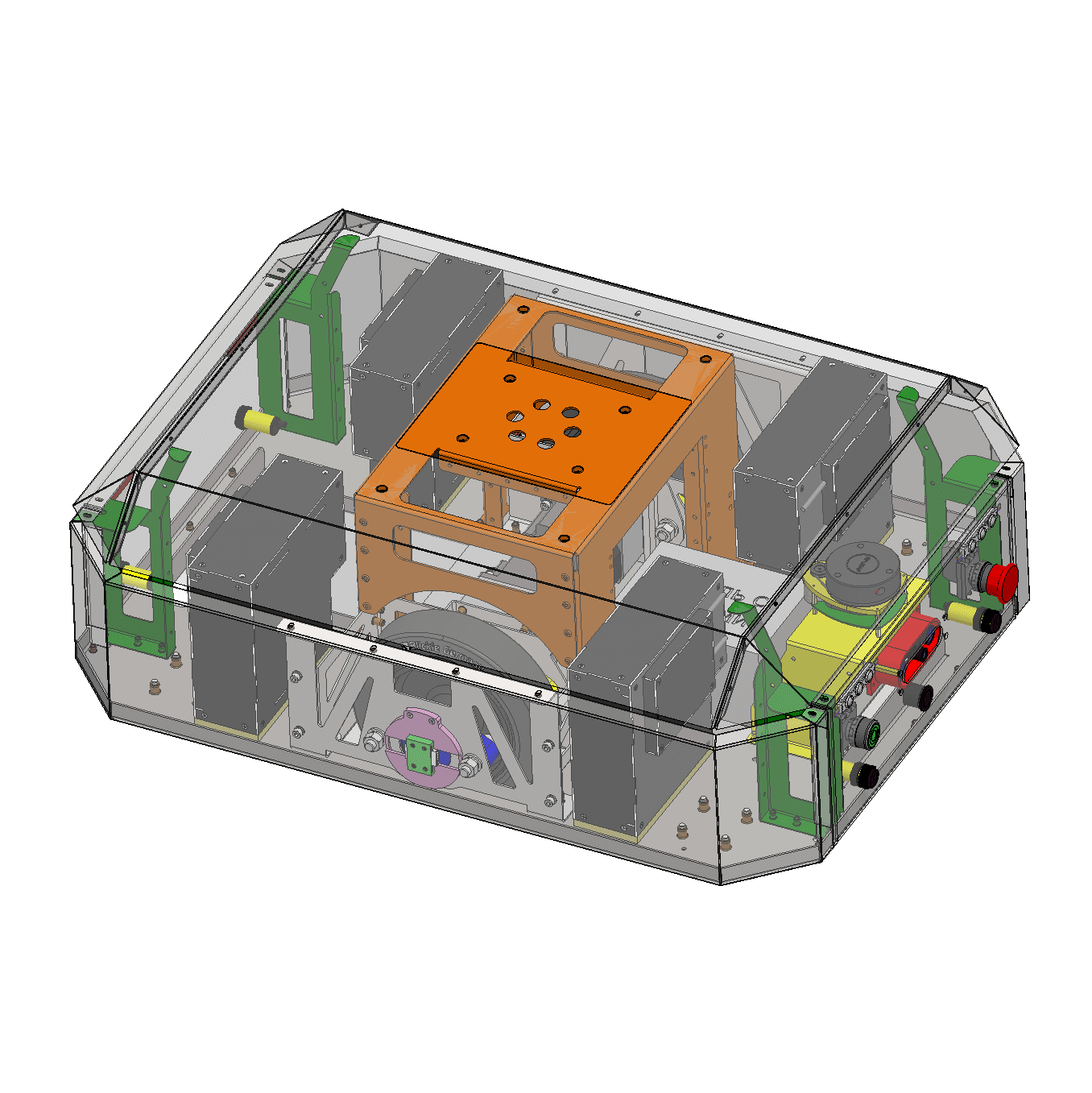
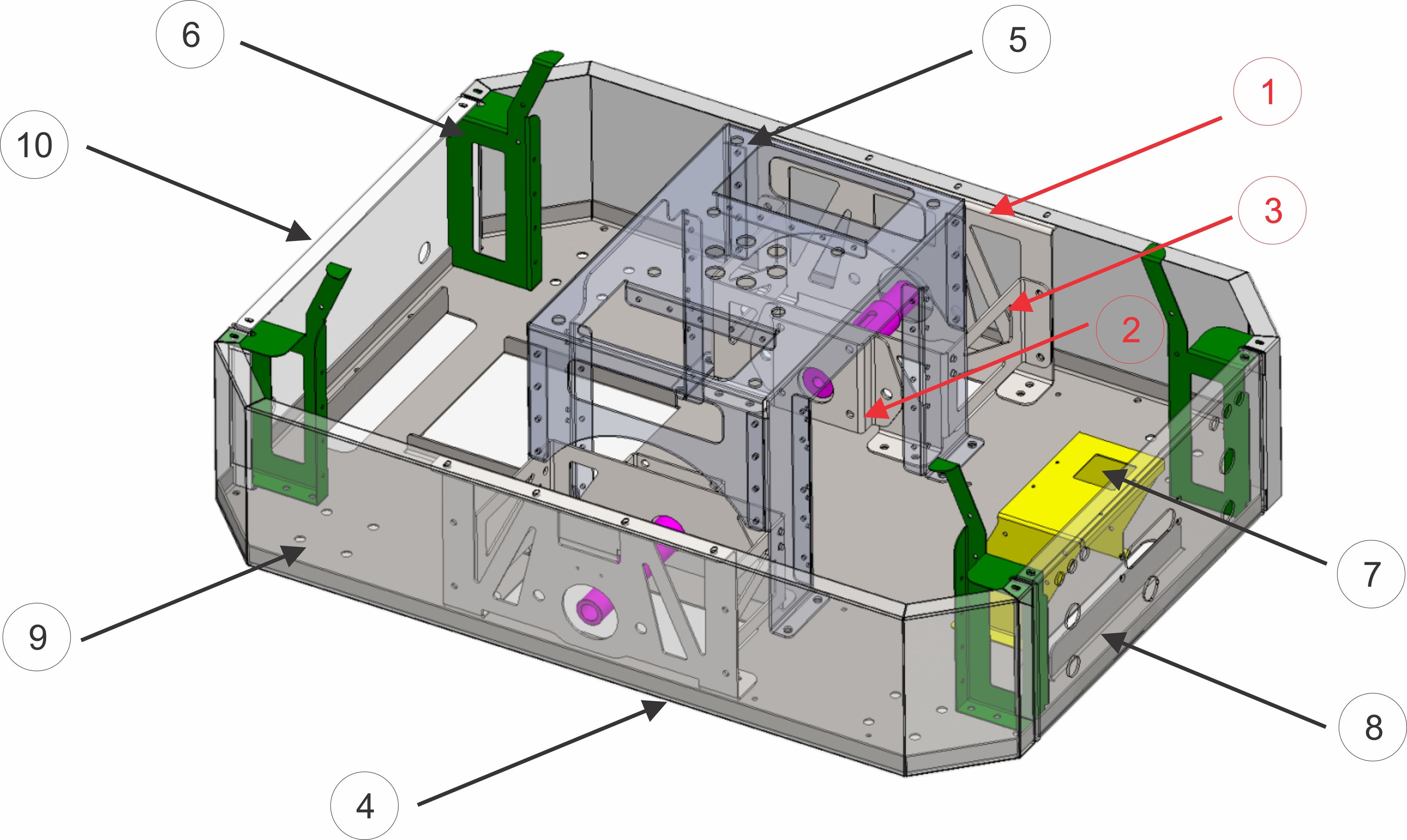
The metal frame of the robot (chassis) consists of 13 unique types of parts, totaling 20 individual components, including symmetrical and repeating ones. The chassis design and the recommended assembly sequence are illustrated in Picture 3.
Discuss the drawings from the folder “Production_files” with a contractor for cutting and bending metal. The document "BOM_specs_MMP.xlsx" and drawings together provides enough detail for any contractors to understand the requirements and produce it. Parts should be laser cut and bent as specified in the drawings.
Picture 3 - Mobile robot chassis overview
We aimed to minimize the number of parts, assemblies, and assembly operations as much as possible. However, there are still more than a dozen components. While we can't cover every assembly in this article, we will provide one example to guide you through the process.
In Picture 3, you can see the main parts and the chassis assembly. The number in the circle represents both the part number and the assembly step in the sequential assembly process.
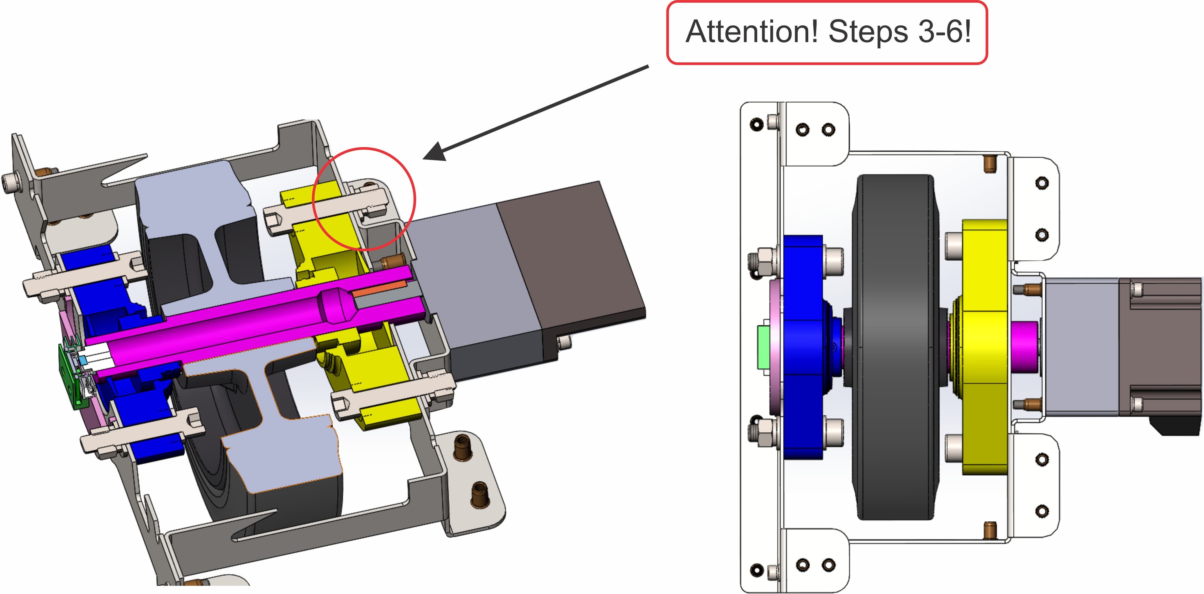
We will examine the numbers marked in red in more detail in the following pictures. These steps represent the most challenging part of the assembly: assembling the drive wheels.
Detailed steps for assembling the drive wheels
Parts required: 1, 2, 3, 4, 5, BLDC motors, bearing housing sets, shafts, wheels, C-clip locking washers, fasteners.
Steps:
- Screw one of the bearing housing sets onto part 1.
- Screw the BLDC motor onto part 2.
- Insert the shaft with a key through the two bearing housing sets and the wheel into the assembly (without fixing the second bearing housing set yet).
- Secure the shaft by fixing it with a retaining C-clip washer (locking washer).
- Use the BLDC motor attached to part 2 and insert the engine shaft with the key into the wheel axle.
- Screw the BLDC motor and part 2 assembly to the part 1 and part 3 assembly.
- This completed assembly can now be attached to base 4.
- Follow the same steps to assemble the second wheel module.
- After both wheel assemblies are installed on the base, proceed to the next step.
- Install the wheel assembly on the central part 5. Fix everything together using screws to complete the chassis assembly.
The entire assembly process described above is also presented here for your convenience.
Picture 4 - Wheel assembly overview
As already mentioned, to simplify this assembly to three steps, you can use a two-shaft motor from ZLTeсh, as shown in Picture 5.
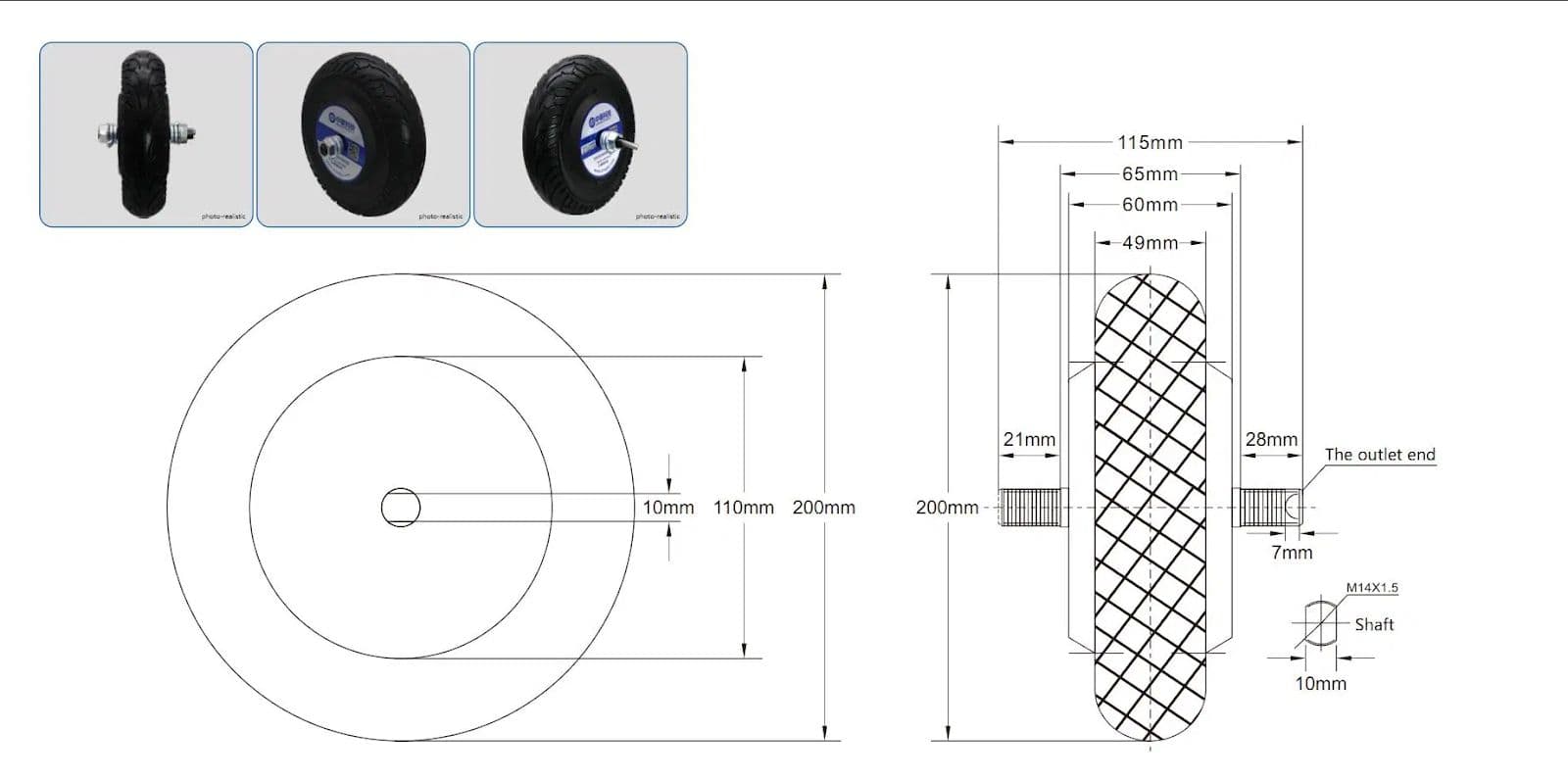
Picture 5: Zltech BLDC Hub wheel motor
This wheel motor has a power of 150 W and a diameter of 200 mm (8 inches). It includes a built-in 1024-bit encoder and comes with a driver from the same manufacturer. All documentation is available in the repository with datasheets in the ZLTech folder. The motor wheel and its driver simplify the assembly of the robot and reduce the overall product cost. The wheels exhibit good wear resistance properties, and their characteristics match the specified claims.
Tools required
Installation of rivet nuts, also known as threaded rivets, can be done using either a manual rivet gun or a pneumatic one.
If your bending machine has a bend radius different from the recommended one (depending on the tool and punch), you may need a file. However, to assemble a mobile robot, you will generally only need a set of screwdrivers, a rivet gun, and a set of wrenches. The operations are simple and intuitive.
Coming up
Next time, we'll dive into:
- Installing electronics and wiring
- Configuring components
- Using Linorobot's open-source software
From beginners to experts, don't miss this exciting step in your robotics journey.
Stay tuned!